Click here for a one-page print-friendly version.
It is useful to remember that a relatively small misalignment in toric lens placement can result in significant loss of astigmatic refractive effect. This relationship is sinusoidal (R=2Csinθ), where R = resulting cylinder of a misaligned toric IOL fully correcting for 1D of astigmatism (C).
The percent values representing loss of effect are listed in Figure 1. Note that at 30 degrees of misalignment, there is complete loss of effect, with the patient retaining 1D of astigmatism, albeit at a different axis.
From a practical standpoint, this means that an accurate marking technique is critical. It is best achieved if we:
- minimize the number of steps (misalignment can occur at any stage of a multi-staged procedure, this error is compounded with each subsequent error) and the extrapolation/interpolation involved
- center markings on the visual axis, not the cornea, which is not circular but ellipsoid
- use a marker/technique that allows easily for single degree alignment (most Mendez gauges and markers are only calibrated for every 5º to10º), and produces a small discrete mark that does not bleed (such as with ink or by vessel nicking)
- reproduce testing conditions (patient position and fixation - there is evidence that either can cause significant cyclotorsion in certain individuals) during the marking procedure
- ensure optical alignment of microscope during marking and intraoperatively during lens alignment, minimize parallax.
My preferred method for marking is a one-step technique (see Figures 3, 4 and 5 below) centered on the visual axis using a slit lamp reticule (or alternatively a graduated degree slit tilt guide available on many slit lamp models) to directly mark the cornea using a 30G needle at the diameter of the toric lens markings (usually 5 mm to 6 mm for aphakic IOLs, slightly further apart for most phakic IOLs). Centering markings on the visual axis aids in centering lens placement, which is potentially even more important for diffractive toric lenses and planned bioptics. I find that operating either on the steep axis or the flat axis simplifies vector calculations and extends the range of astigmatic correction by adding or subtracting surgically induced astigmatism to that of the lens.
Occasionally, surgically induced astigmatism can be unpredictable and/or corneal irregularity can result in difficulty interpreting the available keratometry/topography data and determining the best alignment for minimizing refractive astigmatism. This is especially relevant in the setting of ectatic diseases, such as keratoconus and pellucid marginal degeneration, or after refractive surgery (e.g. radial keratotomy or ectasia). Therefore, we found it useful to derive a formula for determining the rotation in degrees necessary for a misaligned toric IOL to be rotated into its optimal position (adjusted α or Aα), based on knowledge of the patient's post-operative astigmatic refraction (R x β), the power of the astigmatic component of the implanted lens (-C) and its axis θ, from which Δ (between -C and R) can be derived (e.g., see Figures 6. 7. 8 and 9 below).
Figures
Click each image to enlarge.
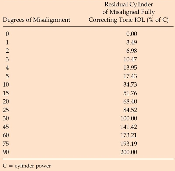
Figure 1. Residual cylinder associated with a fully-correcting toric IOL for varying degrees of misalignment as a percentage of the cylinder power.
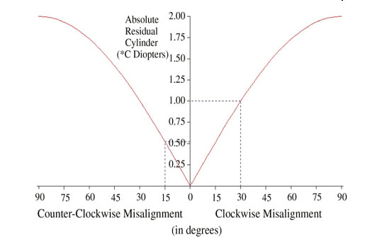 Figure 2. Sinusoidal relationship between residual cylinder (R) and axis misalignment of a fully correcting toric lens of cylinder power C diopters from 0 to 90 degrees. R = 0 if θ = 0 degrees (perfect alignment). R = 200% of C if θ = 90 degrees, R = 51.8% of C if θ = 15 degrees, and R = C if θ = 30 degrees.
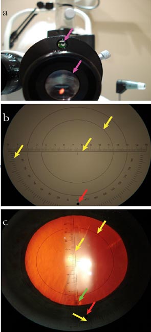 Figure 3. A. Leveling device and reticule. B. Centration ring (top); axis-alignment ruler (center); axis scale (left); angle of alignment, adjustable (red). C. View through eyepiece with epithelial mark (green).
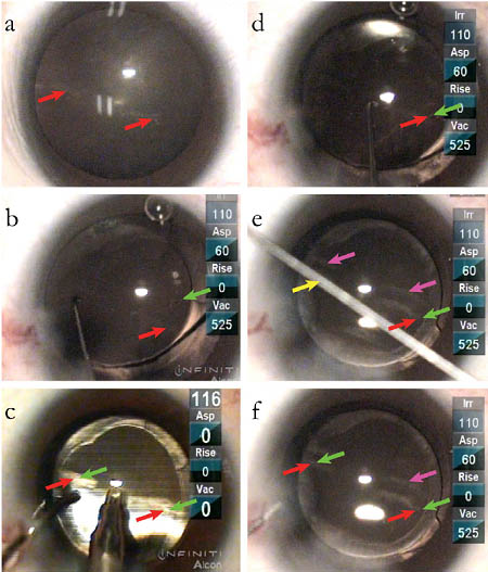 Figure 4. A. Epithelial marks at desired axis and circumference. B. Toric aphakic lens (AcrySof) axis marker (green) before ophthalmic viscosurgical device removal.
C. Ophthalmic viscosurgical device removal during toric lens alignment. D. Fine-tuned rotation. E. Typical method of interpolation with defocused alignment rode (yellow), reflection of marks (purple). F. Confirmation of alignment, markings superimposed.
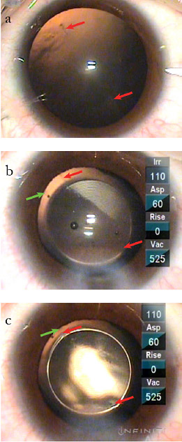 Figure 5. A. Epithelial marks at desired axis and circumference. B. Toric phakic lens (ICL) axis marker (green). C. Toric phakic lens alignment, markings superimposed.

Figure 6. The optimal repositioning of the lens by rotation in degrees for an eye with a total ocular cylinder of +R x β and a lens power of +C x (θ + 90) where Aα (adusted alpha) is an acute-angled rotation from the intial position of the toric lens in the direction of β (the axis of the residual cylinder in positive-cylinder form), and Δ is the angular difference between β and θ.
 Figure 7. Adjusted alpha for the four signed outcomes of Δ and α.
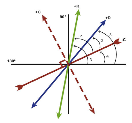 Figure 8. Positive axis of ocular cylinder (+D x λ, blue), negative axis of toric IOL (-C x θ, red inverted), positive axis of toric IOL (+C x {θ + 90}, dotted red,), and positive axis of residual cylinder (+R x β, green).
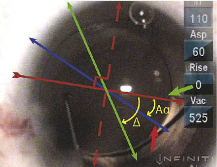
Figure 9. Intraoperative photograph and schematic (axes/angles as in Figure 8), corneal markings denoting axis of ocular cylinder (short red), toric IOL alignment markings (short green).
References
- Ma JJK, Tseng SS. Simple method for accurate alignment in toric phakic and aphakic intraocular lens implantation. J Cataract Refract Surg. 2008;34(10):1631-1636.
- Tseng SS, Ma JJK. Calculating the optimal rotation of a misaligned toric intraocular lens. J Cataract Refract Surg. 2008; 34(10):1767-1772.