The pattern reversal stimulus is the preferred stimulus choice for most clinical situations. The VEPs, elicited to a pattern reversal stimulus (PVEPs), are less variable in waveform and timing than the VEPs elicited by a flash stimulus (FVEPs). In fact, the PVEPs show relatively little variation between subjects with minimal interocular difference variation within a subject, and minimal variation with repeated measurements over time. The PVEPs are useful in detecting optic nerve and/or optic tract anomalies.
Video 3. Pattern reversal stimulus (PVEPs)
The pattern onset/offset stimulus shows greater inter-subject variability compared to the PVEPs. However, it is best suited for the detection or confirmation of malingering and for evaluation of subjects with nystagmus because the technique is less sensitive to confounding factors such as poor fixation, eye movements, or deliberate defocus.
Finally, the flash stimulus is useful when poor optics, poor cooperation, or poor vision makes the use of pattern stimulation inappropriate. The flash stimulus has great benefits when testing babies and infants who cannot fixate. Demonstration of an intact FVEP provides evidence that some visual input has reached the occipital cortex, but does not demonstrate the presence of conscious visual perception.
To comply with standard procedures, at least one of the above mentioned VEPs (FVEPs, PVEPs, onset/offset VEPs) should be included in every clinical VEP testing. In fact, the standard procedures do not require that all three protocols be used for every investigation on every subject. In general, a single stimulus protocol will be appropriate.
Specialized VEP recordings
To standardize the way visual evoked potentials were recorded and to ensure quality and reproducibility of the results across clinical and research laboratories, the ISCEV published standardized procedures to record visual evoked potentials.1,6 Other stimuli can also be used to record visual evoked potentials (Table 1). These specialized VEP stimuli can be used to address more specific dysfunction of the visual pathways. However, at this time, these specialized VEP stimuli are not used in clinical visual electrophysiology VEP testing; these protocols are mostly used in research.
|
Table 1: Specialized visual evoked potentials stimuli.
|
|
Specialized Visual Evoked Potentials
|
Use
|
|
Binocular beat response visual evoked potential
|
Used to measure visual cortex binocularity in amblyopia.
|
|
Chromatic visual evoked potential
|
Used as an indicator of early color vision changes by assessing the integrity of the neural pathways responsible for color vision.
|
|
Hemi-field visual evoked potential
|
To evaluate the VEP responses of each hemisphere separately.
|
|
Multifocal visual evoked potential
|
Used to evaluate independent responses from multiple areas of the visual field simultaneously. It helps the quantification of localized visual field damage.
|
|
Motion visual evoked potential
|
Used in early detection and monitoring of strabismic amblyopia.
|
|
Sweep visual evoked potential
|
To estimate visual acuity in babies, infants, and uncooperative young children.
|
Recording methods
Electrode types
Multiple types of electrodes are available to record visual evoked potentials. However, surface skin electrodes, such as gold disc electrodes or sintered silver-silver chloride (Ag-AgCl) electrodes, are recommended to record VEPs.
Before applying electrodes, the patient’s skin must be properly cleaned and the use of a paste or gel around the electrodes is necessary to ensure a good and stable electrical connection. In most circumstances, the electrode impedance should be below 5 kΩ.
Electrode placement
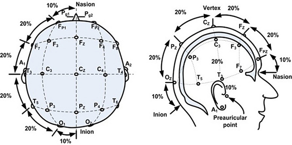
When standard visual evoked potentials are being recorded, testing protocols suggest the use of a single midline occipital active electrode (OZ). However, when chiasmal or retrochiasmal anomalies are suspected, it is recommended to use three occipital active electrodes. The first occipital active electrode should be positioned at midline (OZ) while two other occipital active electrodes should be positioned either right (O1) or left (O2) from the midline electrode (OZ). The occipital active electrodes should be placed following the International 10/20 system (Figure 1). A reference electrode is generally placed at FZ, while a ground electrode is placed at the mastoid/earlobe position or at the earlobe.

Figure 1. International 10/20 system of electrode application. From the open access book Advances in Mechatronics. Mansor W, Shaifulrizal Abd Rani M, Wahy N. Integrating neural signal and embedded system for controlling small motor. 2011; 31-42. http://issuu.com/vnchampion/docs/advances_in_mechatronics.
Recordings parameters
To record visual evoked potentials, the pupils must remain undilated in all subjects. Furthermore, when pattern stimuli are used, corrective lenses must be used if needed to achieve best corrected visual acuity. Usually, the VEP responses are recorded with a minimal analysis time of 250 ms. However, when onset/offset VEP stimuli are used, as well as when children are tested, the analysis time must be extended to 500 ms. Finally, a minimum of 64 responses should be averaged while recording VEPs in subjects. To increase reproducibility and reliability of the VEP results, at least two separate recordings should be performed on each subject.
Stimulus parameters
Flash stimulus
A flash of light should be used to record the FVEPs. Per standard procedures, a short (less than 4 ms in duration) white flash (intensity: 3 cd.sec.m-2) with a stimulus rate of 1 flash per second should be used. The flashes can be sent using either a hand-held device or an integrating bowl (Ganzfeld). Changes in flash duration, intensity, frequency, and color will alter the standard FVEP waveform, so any deviation from the standard procedures should be carefully noted and analysis of the results should be done accordingly.
Pattern-reversal stimulus
The standard pattern reversal stimulus is a high contrast (should be equal to or greater than 80% contrast) black and white checkerboard presented on a computer screen. The black and white checkers should alternate at a rate of 2 reversals per second and at least two different check size stimuli should be used. Standard procedures require that the stimulus subtend a visual angle of 0.25 degree and 1 degree. Finally, subjects should be seated at approximately 50 cm to 150 cm from the stimulator (computer screen).

Figure 2. Schematic representation of a pattern reversal stimulus.
Pattern onset-offset stimulus
The pattern onset-offset stimulus also uses a high contrast (should be equal to or greater than 80% contrast) black and white checkerboard pattern. However, as opposed to the pattern reversal stimulus, the checkers do not alternate. Instead, the entire stimulus (checkerboard) appears (200ms) and then disappears (gray background; 400 ms) from the computer screen. Similarly to the pattern reversal, at least two pattern element sizes should be used (0.25 degree and 1 degree).

Figure 3. Schematic representation of an onset/offset stimulus.
Waveforms
FVEP
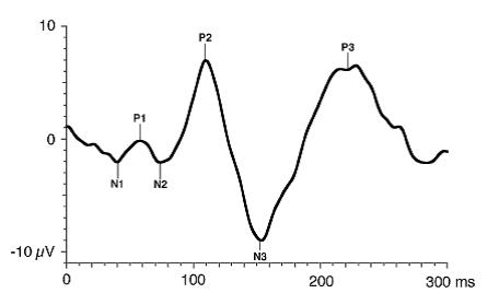
The FVEP consists of a series of six negative and positive waves: N1, P1, N2, P2, N3, P3. As a general rule, the major wave analyzed is P1.

Figure 4. Standard FVEP waveform. Odom JV, Bach M, Brigell M, Holder GE, McCulloch DL, Tormene AP, Vaegan; ISCEV standard for clinical visual evoked potentials (2009 update). Documenta Ophthalmologica. 2010; 120(1): 111-119. Used with permission from Springer Science+Business Media.
PVEP
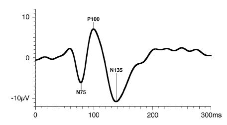
The PVEP consist of three major waves: N75, P100, and N135. As a general rule, the major wave analyzed is the P100 wave.

Figure 5. Standard PVEP waveform. Odom JV, Bach M, Brigell M, Holder GE, McCulloch DL, Tormene AP, Vaegan; ISCEV standard for clinical visual evoked potentials (2009 update). Documenta Ophthalmologica. 2010; 120(1): 111-119. Used with permission from Springer Science+Business Media.
Onset-Offset VEP
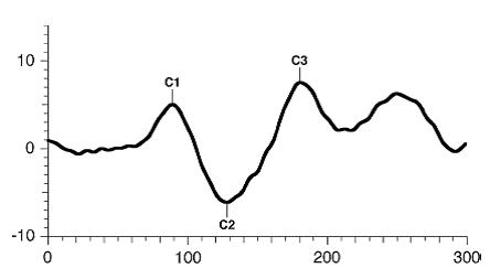
The pattern onset-offset VEP consist of three major waves: C1, C2, C3. As a general rule, the major wave analyzed is the C2wave.

Figure 6. Standard onset/offset VEP waveform. Odom JV, Bach M, Brigell M, Holder GE, McCulloch DL, Tormene AP, Vaegan; ISCEV standard for clinical visual evoked potentials (2009 update). Documenta Ophthalmologica. 2010; 120(1): 111-119. Used with permission from Springer Science+Business Media.
Interpretation/Reporting
Basic interpretation
Visual evoked potential (VEP) waves are analyzed in peak time (also referred to as latency or implicit time) and in amplitude. The amplitude of the first VEP wave is always measured from the pre-stimulus baseline to the peak of the wave under evaluation. All other waves are calculated from the peak of the preceding wave to the peak of the wave under evaluation. Peak times are measured from the flash onset to the peak of the appropriate waveform component. Overall, peak times are more reliable than amplitudes. In normal subjects peak time variability is approximately 2 to 5 % within and between recording sessions, whereas amplitudes can vary by as much as 25% within and between subjects.
VEP amplitude is a measure of the size of the response, whereas VEP peak time reflects transmission time from the retina to the occipital cortex after the onset of stimulation. Decreases in VEP amplitude generally result from a reduction in the number or sensitivity of neurons in the retinocortical pathway. Increases in VEP peak time may reflect abnormal retinal transmission, defects in the myelin of the visual pathway from the optic nerve to the occipital cortex, or even synaptic abnormalities in the occipital cortex.
Advanced interpretation
Interpretation of VEP can be tedious at times, depending on the subject’s cooperation, visual acuity, age, medication, media opacity, etc. In fact, many factors affect the VEP’s major components and should be carefully reviewed before commenting on VEP responses.
This is why it is important to ensure that each visual electrophysiology laboratory establishes its own normative VEP values using its own stimulus and recording parameters. Given the multiple factors that can affect VEPs, it is also important when building a normative database to include factors such as age, refractive error, media opacity, etc.
Visual acuity
When a pattern stimulus is used to record a VEP, it is imperative that the subject be tested with best corrected visual acuity. In fact, uncorrected refractive errors will significantly affect the VEP results.7 In subjects where the vision is blurred due to uncorrected refractive errors, the VEP elicited to pattern stimuli with small check sizes will be delayed. Therefore, careful evaluation of PVEPs is necessary to determine if delayed responses are the result of uncorrected visual acuity or the result of an optic nerve/tract problem.
Pupil size
Similarly to when a subject has uncorrected refractive errors, a decrease in pupil size will result in a delay of the VEP when evoked to a pattern stimulus. The latter can be explained by a decrease in retinal illuminance. In fact, the peak times can be shorter by nearly 20 ms when pupil diameter increases from 1 to 9 mm.8 Other factors that may impact retinal illuminance (ptosis or tinted lenses) should also be considered when interpreting VEP elicited to pattern stimuli.
Gender
The peak time of the VEPs evoked to a pattern stimulus is affected by gender. Several studies have reported that women have greater VEP amplitudes and slightly shorter VEP peak times compared to men when a pattern stimulus is used.9
Age
Visual evoked potential parameters in babies, infants, and children reflect not only pathological processes but also maturation of the visual system. Special attention must be paid when evaluating electrophysiological parameters in children because maturation of the visual system, and not pathological processes, could be the cause of possible changes.
Maturation of the VEP is reflected in the waveform peak time, amplitude and morphology. Age-dependent changes have been shown to be considerable in infants. In fact, when the VEP are evoked to a large check size pattern reversal stimulus, the peak time of the VEP reaches adult-like values when the subject is approximately 1 year old. However, when a smaller check size pattern reversal stimulus is used, the VEP peak time only reaches adult-like values when the subject is 5 years of age.9, 10, 11
In fact, PVEP peak times shorten exponentially from birth to 6 months of age and then only slightly shorten until 5 years of age. Peak times may shorten during adolescence but change very little thereafter until they increase slightly after the sixth decade of life.
In the pediatric population, when there are concerns about cortical visual impairment or delayed visual maturation, it is recommended to wait until the child is at least 6 months old before recording the PVEP.
Media opacity
Media opacities such as cataracts, vitreous opacities, etc. will affect the VEP responses, especially the ones evoked to pattern stimuli. In fact, as the media opacity increases, the peak time of the VEP will increase and its amplitude will decrease.12
Retinal dystrophies
It should always be kept in mind that the VEP is a downstream response that arises largely in the visual cortex and can be affected by disease anywhere upstream in the visual system (eg, the retina). Retinal dystrophies including but not limited to central serous retinopathy, macular diseases, and glaucoma have been reported to affect VEPs. In fact, any conditions that affect central vision are likely to affect the VEP, especially when small check sizes are used. Therefore, caution in suggested when analyzing VEP in patients with retinal anomalies.13
When used in conjunction with the electroretinogram (ERG) and/or the multifocal electroretinogram (mfERG), the VEP becomes clinically useful in distinguishing retinal versus optic nerve sites of dysfunction in subjects with only subtle visual disturbances and minimal fundus anomalies.
Medication
Some medications can have a deleterious effect on VEP waves. Most likely the VEP peak times will be delayed in patients taking medications such as ethambutol, cisplatin, and deferoxamine, to name a few, will be delayed.14, 15, 16 Before interpreting VEPs, a thorough review of the literature is always necessary.
Clinical application
Visual evoked potentials alone are of no clinical value unless they are correlated with clinical findings. Similar VEP results can be found in multiple disorders, and without correlation with clinical findings or other tests, it is impossible to make a clear diagnosis.
Optic neuropathies (demyelinating, compressive, toxic, traumatic, ischemic, inflammatory, hereditary)
As a general rule, visual evoked potentials are usually abnormal in optic neuropathies. It is likely that the peak times will be delayed. Even though VEPs are not necessary in the diagnosis of optic neuropathies, it can be useful in subjects with early or subclinical optic neuropathies, who may have normal pupillary responses and no optic disc changes on clinical examination. The mode of onset of visual loss in optic neuropathies is an important clue to the etiology of the anomaly. A more rapid onset of the anomaly is mostly characteristic of optic neuritis, ischemic optic neuropathy, inflammatory optic neuropathy, and traumatic optic neuropathy. A more gradual onset of the anomaly, often over a few months, is more typical of a compressive optic neuropathy.17
Albinism
Misrouting of optic nerve fibers at the optic chiasm is an anomaly associated with albinism. This misrouting results in anomalous decussation of temporal optic nerve fibers and consequently abnormal projection of fibers to the occipital cortex. In fact, there is excessive crossing of optic nerve fibers at the chiasm. Therefore, when VEPs are tested with electrodes placed on both the left occipital lobe and the right occipital lobe, the responses have inverted polarity when the left eye and the right eye stimulation are compared at each hemisphere.18
Amblyopia
In amblyopic patients, the VEPs evoked to pattern stimuli from the amblyopic eye are generally smaller in amplitude compared to the VEPs recorded from the sound eye. However, note that different types of amblyopia can result in different VEP findings. In fact, in patients affected with anisometropic amblyopia, the VEP responses recorded from the amblyopic eye are generally smaller compared to the VEPs recorded from the sound eye. However, in subjects affected with strabismic amblyopia, normal VEPs can be recorded from both the amblyopic eye and the sound eye.19 Careful attention to the type of amblyopia is necessary when evaluating VEPs in amblyopic subjects.
Conclusion
VEPs are often used in ophthalmology and neurology in cases of unexplained vision loss. They are used to detect, quantify, and monitor abnormalities of the intracranial visual pathways, including the optic nerves, the optic chiasm, and the visual cortex. However, it is important to keep in mind the abnormalities seen in VEPs are only suggestive of an , but are not diagnostic of a specific disorder. VEP abnormalities do not specify etiology. There are multiple factors that can affect the VEP responses, including retinal disease, age, and gender, just to name a few. Interpretation of VEPs must be considered within the context of the subject’s clinical appearance and the information available from other tests and examinations.
References
- Odom JV, Bach M, Brigell M, Holder GE, McCulloch DL, Tormene AP, Vaegan. ISCEV standard for clinical visual evoked potentials (2009 update). Doc Ophthalmo. (2010); 120:111-119.
- Adrian ED, Mathews BHC. The Berger rhythm: Potential changes from the occipital lobes in man. Brain. 1934; 57:365-385.
- Halliday AM, McDonald WI, Mushin J. Delayed visual evoked response in optic neuritis. Lancet. 1972; 1:982-985.
- Halliday AM, McDonald WI, Mushin J. Visual evoked response in the diagnosis of multiple sclerosis. Br Med J. 1973; 4:661-664.
- Halliday AM, McDonald WI, Mushin J. Delayed pattern evoked responses in optic neuritis in relation to visual acuity. Trans Ophthalmol Soc UK. 1973; 93:315-324.
- International Society for Clinical Electrophysiology of Vision. Standards, Recommendations, and Guidelines. http://www.iscev.org/standards/index.html.
- Sokol S, Moskowitz A. Effect of retinal blur on the peak latency of the pattern evoked potential. Vision Res. (1981a); 21: 1279-1286.
- Sokol S, Domar A, Moskowitz A, Schwartz B. Pattern evoked potential latency and contrast sensitivity in glaucoma and ocular hypertension. In: Spekreijse H., Apkarian P.A., eds: Electrophysiology and pathology of the visual pathways. Hague: Dr w junk BV Publishers. Doc Ophthalmol Proc Ser (1981b); 27: 79-86.
- Brecelj J. From immature to mature pattern ERG and VEP. Doc Ophthalmol. 2003; 107:215-224.
- Sokol S, Mokowitz A, Towle VL. Age-related changes in the latency of the visual evoked potential: influence of check size. Electroencephalogr Clin Neurophysiol. 1981c; 51:559-562.
- Mokowitz A, Sokol S. Developmental changes in the human visual system as reflected by the latency of the pattern reversal VEP. Electroencephalogr Clin Neurophysiol. 1983; 56: 1-15.
- van Lith GH, Hekkert-Wiebenga W. Cataract, pattern stimulation and visual evoked potentials. Doc Ophthalmol. 1983; 55:107-122
- Fishman GA, Birch DG, Holder GE, Brigell MG. Electrophysiologic Testing in Disorders of the Retina, Optic Nerve and Visual Pathway. Ophthalmology Monograph Series, 2nd edition; 2001:237-280.
- Woung LC, Jou JR, Liaw SL. Visual function in recovered ethambutol optic neuropathy. J Ocul Pharmacol Ther. 1992; 11:411-419.
- Maiese K., Walker R.W., Gargan R, Victor JD. Intra-arterial cisplatin-associated optic and otic toxicity. Arch Neurol. 1992; 49:83-86.
- Marciani M.G., Cianciulli P., Stefani N., et al. Toxic effects of high dose deferoxamine treatment in patients with iron overload: an electrophysiological study of cerebral and visual function. 1991; 76:131-134.
- Behbehani R. Clinical approach to optic neuropathies. Clin Ophthalmol. 2007; 3:233-246.
- Apkarian P. Albinism. In: Heckenlively JR, Arden GB (eds): Principles and practice of clinical electrophysiology of vision. Mosby, St. Louis (1991) 773-782.
- Beneish R, Lachapelle P, Polomeno R, Lake N. Pattern VEP differences in strabismic and anisometropic amblyopia. Clin Vision Sci. 1990; 5:271-283.